|
|
|
|
|
|
||
| |||||||||||||||
|
Installation Technical Support INTRODUCTIONThe location chosen for the water heater must take into consideration the following: LOCAL INSTALLATION REGULATIONS: This water heater must be installed in accordance with these instructions, local codes, utility company requirements, and/or in the absence of local codes, the latest edition of the American National Standard, National Fuel Gas Code. A copy can be purchased from either American Gas Association, 1515 Wilson Blvd., Arlington, VA 22209 as booklet Z223.1 or National Fire Prevention Association, Batterymarch Park, Quincy, MA 02269 as booklet NFPA No. 54. 1. A gas fired water heater should not be installed in a space where liquids which give off flammable vapors are to be used or stored. Such liquids include gasoline, L.P. Gas (butane and propane), paint and adhesives and their thinners, solvents or removers. Because of natural air movement in a room or other enclosed space, flammable vapors can be carried some distance from where their liquids are being used or stored. The open flame of the water heater’s pilot light or main burner can ignite these vapors causing an explosion or fire which may result in severe burns or death to those in range, as well as property damage. For these reasons installation of a gas fired water heater in a garage is not desirable. If a location in the garage is the only alternative, the gas fired water heater should be installed so that the open flame of the pilot and main burner are no less than 40 inches above the garage floor. Raising the gas fired water heater will reduce BUT NOT eliminate the possibility of lighting the vapors of any flammable liquids which may be improperly stored or accidentally spilled. 2. The water heater should be installed as close as practical to the gas vent or chimney. Long hot water lines should be insulated to conserve water and energy. The water heater and water lines should be protected from freezing temperatures. DO NOT the water heater in bathrooms, any occupied rooms normally kept closed nor in outdoor unprotected areas. 3. The water heater must be installed with the minimum clearances to combustible material of 6 inches at the sides, 2 inches at the rear and 16 inches above the top of the draft hood outlet. For alcove installation, the water heater shall be installed above noncombustible flooring.
4. CAUTION! The water heater should not be located in an area where leakage of the water heater will result in damage to the area adjacent to it or to lower floors of the structure. When such areas cannot be avoided, it is recommended that a suitable catch pan, adequately drained, be installed below the water heater. The pan MUST NOT restrict combustion air flow.
5. COMBUSTION & VENTILATION AIR: Proper operation of the water heater requires air for combustion and ventilation. If the water heater is installed in an unconfined space within a building of conventional frame, masonry or metal construction, infiltration air is normally adequate for proper combustion and ventilation. The confined space should be provided with 2 permanent openings: one commencing within 12 inches of the top and one commencing within 12 inches of the bottom. Each opening should have a total free area of not less than that as follows depending upon the type of installation. (a) If all air for combustion comes from inside the buildings: Each opening should have a minimum free area of 1 square inch per 1,000 Btu per hour of the total input rating of all gas utilization equipment in the confined space, but not less than 100 square inches. (b)
If all air for combustion comes from outdoors:
Protective screening for the openings MUST NOT be smaller than 1/4 inch mesh to resist clogging by lint or debris. Provisions
for combustion and ventilation air must comply with the referenced codes and
standards. The water heater should not be installed near an air supply containing halogenated hydrocarbons. For example, the air in beauty shops, dry cleaning establishments, photo processing labs, and storage areas for liquid and powdered bleaches or swimpool chemicals often contain such hydrocarbons. The air there may be safe to breathe, but when it passes through a gas flame, corrosive elements are released that will shorten the life of any gas burning appliance. Propellants from common spray cans or gas leaks from refrigeration equipment are highly corrosive after passing through a flame.
8. METHOD OF INSTALLATION:
INSTALLATIONS
Inspect water heater for possible damage. Check the marking of the rating plate of the water heater to be certain the type of gas being furnished corresponds to that for which the water heater is equipped. a. The water supply to the water heater should be such as to provide sufficient pressure to properly operate the water actuated control valve. The minimum working water supply pressure is shown in the table. However, additional supply pressure is required above the minimum pressure to cover any pressure head loss or drop in hot water supply lines. Make sure that the total water pressure at the inlet is sufficient to operate water heater at full capacity.
b.
Install a shutoff valve near the water inlet of the water heater for purpose of
the servicing and draining.
c. Connection between the water heater and places where hot water is used should be as short and direct as possible, and a uniform pipe size of sufficient diameter to carry the full capacity of hot water should be used. d. Be sure to connect the water inlet and the hot water outlet as shown on the water heater. If reversed, the water heater will not function.
e. When hot water flows through the supply line there is an invisible heat loss, regardless of type of water heater. Thus, insulation or protection of hot water piping is encouraged.
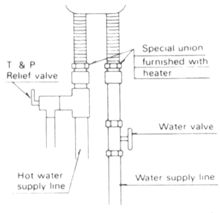
A new combination pressure and temperature relief valve, complying with the Relief Valve Standard, ANSI Z21.22-1986, must be installed at the hot water outlet connection of the water heater at the time of installation. Local codes should govern the installation of the relief devices. For safe operation of the water heater, be sure that: ( I
) No valve is placed between the relief valve and the water heater.
a.
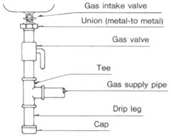
The gas supply lines should be gas-tight and of such size, and so installed, as
to provide a supply of gas sufficient to meet the maximum demand of the water
heater without undue loss of pressure.
f. After the water heater is connected to the gas supply, all connections including water heater must be checked for leakage with soapy water, bubble solution or other acceptable means before placing the water heater in operation. DO NOT use Matches, Candles or other sources of ignition for the purpose of leakage test. g. The appliance must be isolated from the gas supply piping system by closing its individual manual shutoff valve during and pressure testing of the gas supply piping system at test pressures equal to or less than 1/2 psig (3.5 kPa).
The water heater should be connected to a gas venting system constructed so as to adequately remove flue gases to the outside atmosphere. a. The vent connectors must be attached to the draft hood outlet to connect the water heater to the gas vent or chimney. The vent connectors must be the same size (diameter) as the draft hood outlet or larger, never smaller. For proper venting in certain installations a larger vent connector size may be needed. Consult Vent Tables in Appendix "G" of the National Fuel Gas Code (ANSI Z223.1 of NFPA booklet 54).
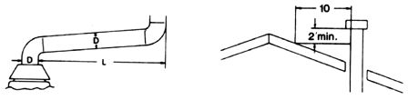
b. The terminal of the flue pipe should be extended at least 2 feet above the highest point where it passes through a roof of a building and at least 2 feet higher than any portion of a building within a horizontal distance of 10 feet. c. Horizontal vent connectors must be pitched upward to the chimney at least 1/4" per foot of length. d. Single wall vent connectors must be at least 6" from adjacent unprotected combustible surfaces. Joint of vent connectors should be securely fastened by sheet metal screws or other approved method. e. The location of the pipe passing through a wall should be protected by noncombustible material to provide sufficient clearance from the pipe. f. All portions of the pipe should be adequately supported for the design and weight of the material employed. g. A cap or a roof assembly should have a venting not less than that of the pipe to which it is attached. h. DO NOT install the flue outlet in a wind pressure drift area as shown below.
A venting system should be designed and constructed so as to develop a positive flow adequate to remove flue gases to the outside atmosphere.
INSTALLATION CHECK LISTA. Water Heater Location
B. Water Supply
C. Relief Valve
D. Gas Supply
E. Venting
|
| ||||